
 Geotechnical investigation is a process of soil / rock sampling and testing to determine the stratification and engineering properties of the site underlyingfor designing purposes. The principal of interest will be the strength, deformation and hydraulics characteristics. Generally, these informations shall provide recommendations for foundation,settlement, groundwater issues, permeability, slope stability, retaining wall, dewatering, and any other potential problems. Investigation of the underground conditions at a site is prerequisite in almost any construction structures such as buildings, bridges, roads, dams, power plants, tunnels, ports, pipelines, and many others.
The importance of this investigation is beyond technical requirement; as such a proper planned investigation will lead to economical design of substructure elements.
Our geotechnical investigation services consist of :
Borehole (hand bore, coring, washbore, percussion and auger systems) to take soil /rock samples both undisturbed and disturb samples.
Insitu testing of: standardpenetration test (SPT), field vane shear test (FVST), permeability test, packer test, penetrometer and point load test.
Standard penetration test analyzer with instrumented rod.
Groundwater level monitoring and sampling.
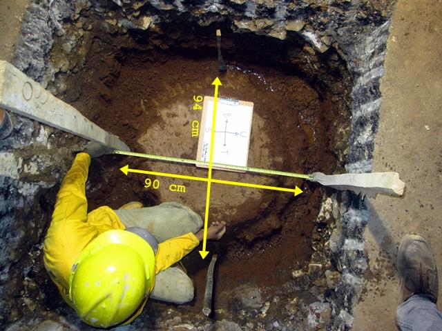
Test pit (TP)
Cone penetration test (CPT) both with mechanical and electrical cones (CPTu / piezocone with dissipation test).
Plate bearing test (PBT)
Pressurement test (PMT)
Dilatometer test (DMT)
Pumping test (long term method)
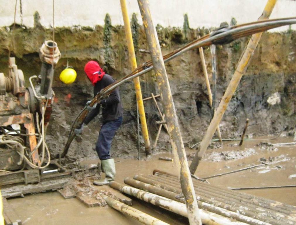
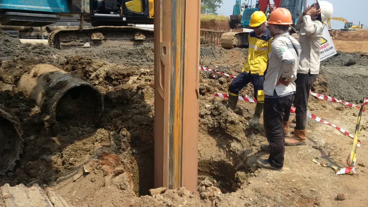 Bored pile is a cast-in-situ pile, constructed by making a cylindrical holein the ground to the required depth and subsequently filling it with reinforced concrete or other proprietary units. This type of foundation often referred as replacement pile is suitable for areas requiring minimum disturbance of ground heave and vibration,such as proximity with existing structures. Pile length and diameter (from small 0.4 m until large 2.5 m or more) can be readily varied to suit varying ground conditions, making bored piles the most commonly adopted foundation type for heavy structures. Often in bored pile constructions encounter loose and collapsible soil during drilling; as such a temporary steel casing (short or full casing system) shall be inserted into the hole, or alternatively using bentonite or polymer slurry to stabilize it from cave in. Particularly in offshore works, permanent casings are normally compulsory to construct bored piles.
One of the methods to improve the bearing capacity of bored pile is by base enlarging (under reamed) using a belling bucket to create bell shape at the base. Another method is a secondary post grouting either at the shaft or base pile, by injecting grout materials through tube a manchette after pile concreting, to spread across the soil at the shaft or base pile. Such piles can develop considerable end bearing and uplift capacity.
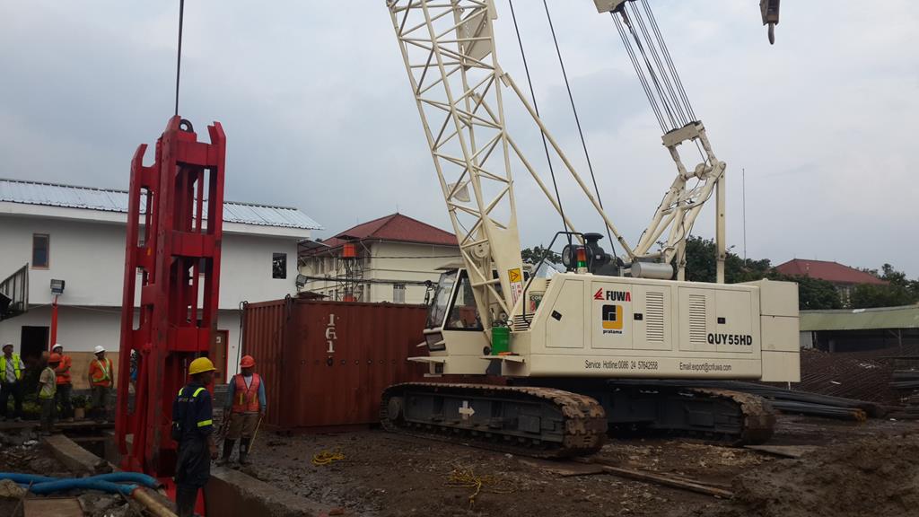
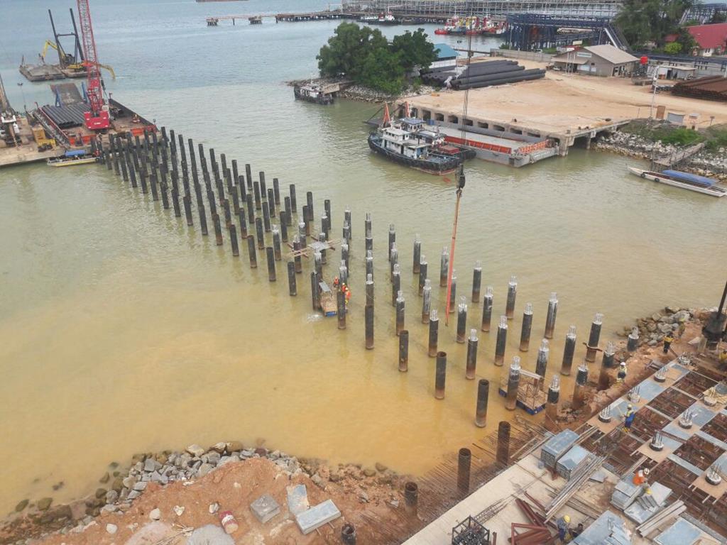 Pile is a structural element of a deep foundation, driven into the ground to transmit surface loads to a subsurface layer or a range of depths in the soil mass. The pile material can be made out of timber, steel, reinforced and prestressed concretes. Driving piles compare to drilling shafts, is advantageous because the soil displaced by driving the piles compresses the surrounding soil (displacement pile), resulting greater friction and increasing load bearing capacity. There are commonly five types of pile driving hammer: 1) drop hammer, 2) diesel hammer (single and double acting), 3) hydraulic hammer which produces less noise and vibration than diesel, and does not emit exhaust fumes, 4) vibro hammer which best suited for sandy or gravelly soils, and 5) Jacking hammer which provides no vibration and noise nuisances and best applicable for urban areas.
Piling can be done either vertically or at an angle to the vertical (raked pile), depending on the pile driving technique. The latter is commonly adopted in offshore structures which are subjected to greater lateral loads.
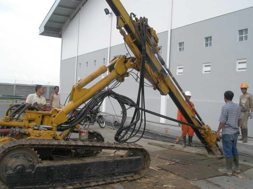 Injection pile or micropile in principal is constructed by injecting a grout materialinto the soil, after drilling a relatively small hole diameterof pile (less than 0.3 m) and forming a pregrout annulus.The action of injection will enlarge the pile hole making the pile into buldging shape like.The combination of grouting and enlargement effects will provide much improved skin friction and end bearing capacity.The capacity can be increased further by increasing the grouting pressure.The application of this pile is commonly for foundation, underpinning and anchor.
This method can be applied from soft to hard soil, and has advantages of no heavy equipments required, no vibration nuisance and veryminimum sound polution.This method is very suitable for construction with difficult access, in the sway areas, in the river or mountain, in narrow places, urban areas, between or in the houses/buildings.
 Pile testing is necessary for any foundation construction to ensure the quality of the installed piles and to proof the designer’s estimate of pile capacity and settlement meet the requirements.
a. Pile driving analyzer (PDA), is a highstrain dynamic load test method (non destructive) to assess the capacity and qualityof pile, and also driving stresses and hammer energy when monitoring installation.
b. Pile integrity test (PIT), is a low stain dynamic load test method or also known low strain impact integrity test (non destructive), used for assessing the integrity of piles or shafts.
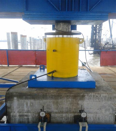
c. Pile static loading test (SLT), the most realiable method to check a pile capacity is to actually load test it. The test is simply conducted by replicating the designed actual load to the pile and analyze its performance. Three types commonly performed: axial compression, axial tension, and lateral load tests. For axial compression test, there are three methods to perfom: kentledge method, reaction pile method and bi-directional axial (O-cell) method.
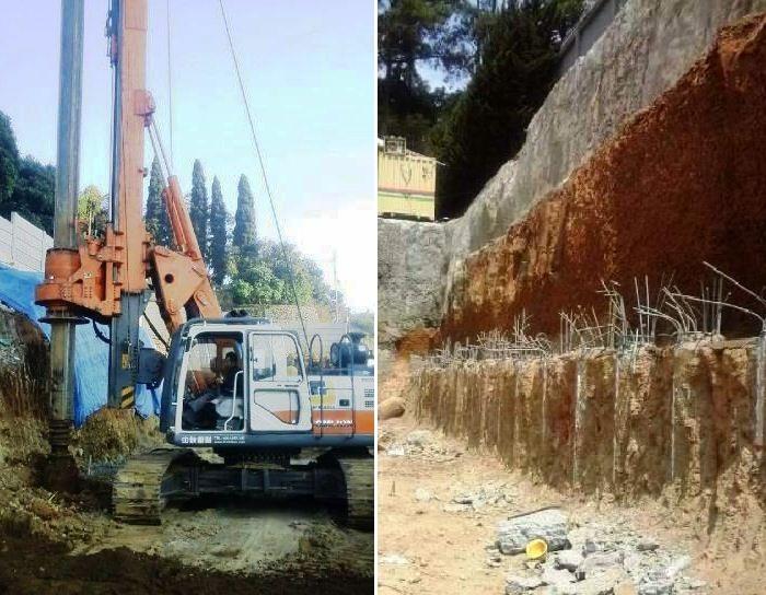 This type of retaining wall is formed by a row of bored piles installed in some spacing or close contact with one another. Soldier piles are usually installed at wide spacing (3 - 5 times pile diameter depending on soil conditions), while contiguous piles are installed at close spacing (less than 1 pile diameter). The exposed soil during excavation can be self supporting or retained by a shotcrete depending on ground conditions. This piles can be applied for temporary as well as permanent wall for deep excavation and suitable for varies of soil conditions.
For conditions where groundwater lies above the excavation level or the retaining wall design shall exclude any heavy inflow behind the wall, a bentonite-cement pile between the bored piles can used to provide an impermeable layer. The intermediate piles will interlock with the bored piles and form a wall similar to a Secant system of interlocking bored piles (concrete to concrete). This method is often applied as an alternative of secant pile wall.
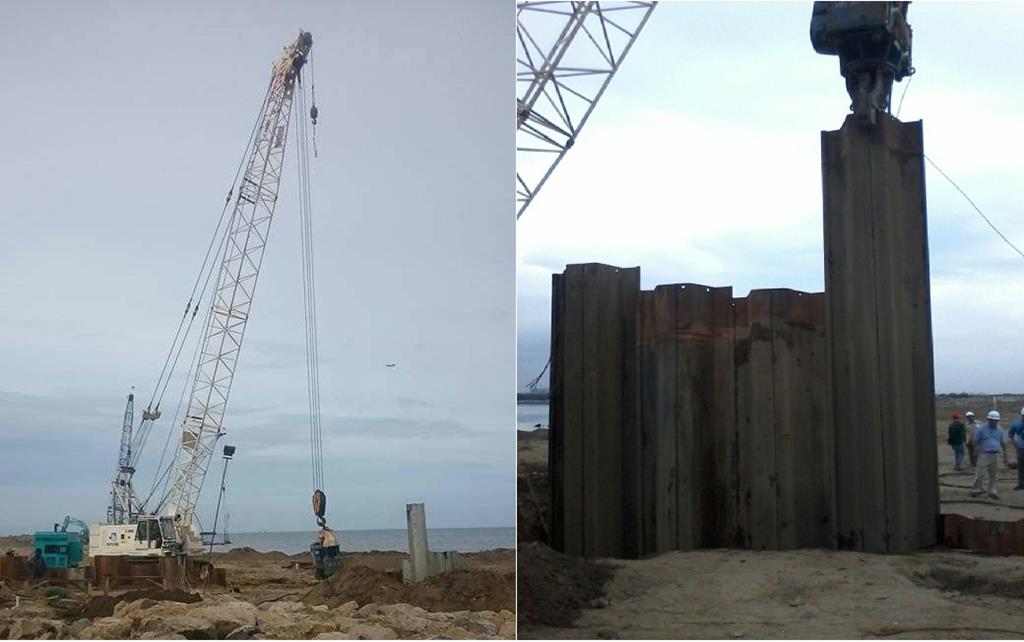 A sheet pile wall is constructed by driving series of sheet piles connected to one another by locking mechanism, into a depth sufficient to develop a cantilever beam type reaction to resist the active pressure on the wall. The sheet pile material widely available is usually from steel with various shapes depending on the design and requirement, and also concrete precast piles.
The most commonly driving method used for sheet piling is by vibration. Not only for installation, a vibro hammer can be used for extracting sheet piles which are necessary for short term use, and the verticality and straightness of sheet piles can be adjusted with this method. Alternatively, a diesel hammer can also be used but for installation only as in the case of permanent type use. For difficult soil especially into sand or sandy gravel stratum, water jetting at the base of sheet pile may be used to aid the penetration.
 A secant pile wall is formed by constructing a row of interlocking female (primary) and male (secondary) bored piles (concrete to concrete). The sequence is carried out with the primary pile installed first then cut (typically 0.15 to 0.2m) by the secondary pile forming a continuous wall and watertight at some degrees. The diameter of pile is usually ranges from 0.8m to 1.2m. The primary pile is cast from either weak mix concrete (less than 15 MPA) or full strength concrete, while the secondary pile as the main structural member is cast from full strength reinforced concrete. Particularly for high strength primary pile, a high torque drilling rigs and special drill casings and extractors are required.
A guide wall is compulsory for this method to ensure the piles accurately positioned to achieve the interlocking cut. This piles can be applied for temporary as well as permanent wall for deep excavation and suitable for varies of soil conditions.
 A diaphragm wall is constructed by excavation in a narrow trench using a grabber or cutter depending ground conditions which is temporarily supported by a bentonite / polymer slurry, and followed with installing steel reinforcement and concreting to replace the slurry. The excavation of the trench is undertaken in alternate panels, with each length is usually about 4m to 6m in stable ground and the width design ranges from 0.6m to 1.2m thickness. To provide a watertight wall, the joint between panels is sealed with a water stop material (installed prior to concreting) or using grouting method. Alternative to cast-in-situ, precast concrete panels can be also used. A guide wall is very important for this method to accurately line the grabber and ensuring a proper watertight joint achieved.
Diaphragm walls are best suited for urban areas that requires deep excavations and in the proximity of existing structures or building, such as deep basements, tunnel approaches, underground rail stations and often used in top down constructions. As a permanent retaining structure, for deeper excavation diaphragm wall is considered more economical compare to the secant pile system.
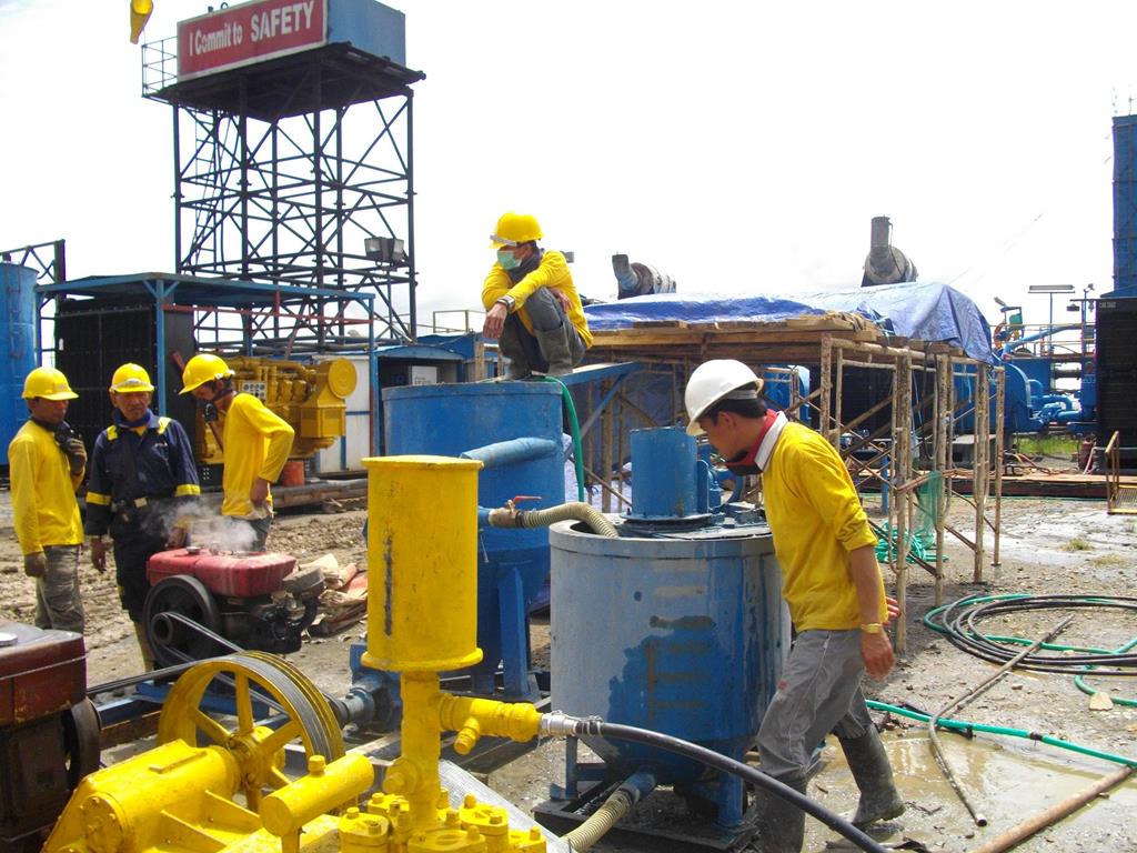 Grouting is a technique to improve problematic soft and loose soils in cohesion, density and permeability or fractured rocks by injecting grout material of cementitious or chemicals types depending on requirements. It can be accomplished by numerous methods such as end of casing, tube a manchette (TAM), limited area grouting (LAG), and jetting.
There are four types of grouting; 1) Compaction (displacement), to inject grout at high pressure to densify the soft or loose soil forming a very dense and coherent bulb at discrete locations. 2). Permeation, to introduce grout into soil pores or rock fractures to improves its properties without any essential change in the original soil volume and structure. 3). Hydrofracture (claquage), to inject grout at high pressure to fracture or split the soil and forming lenses and sheets of grout. 4) Replacement, to mix the soft or loose soil with grout by changing the structure and properties and produce a new hard or dense and impervious layer.
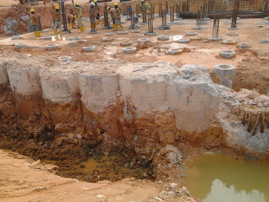
 Jet grouting is a soil improvement method to enhance soil engineering properties by cut, removed and mixed in-situ with cementitious grout or other hardeners using high pressure (jetting), and in time solidified providing high strength and impermeable homogenous soil mass columns. The main advantage of jet grouting is that it can be applied for whole ranges of soils from coarsest gravels to the finest clays. The designated improved soil properties can be well designed, controlled and achieved, providing cost effective solution. Jet grouting only requires relatively small borehole to create larger diameter improved soil column, it can be conducted from any suitable access point (urban area), terminated at any elevation, and conducted vertically or (sub). The diameter grout column available ranges from 0.8m until 3m depending on the soil condition. Other than for soil improvement and impermeable layer, jet grouting method can be applied also structural support such as foundation, retaining wall and slope stability.
Deep mixing is a soil improvement method to enhance soil engineering properties by mixed in-situ with cementitious grout or other hardeners using mechanical mixing blade and low pressure grouting, to create improved soil mix columns. The mixing concept is similar and as the predecessor of jet grouting method, with relatively less improvements and application flexibility, however much more economical. Virtually all soil deposits can be treated, except for those which contain rocks or boulders, or other debris which prohibit penetration by the drilling and mixing tools. The diameter soil mix column available ranges from 0.6m until 1.6m depending on the soil condition. Other than for soil improvement and impermeable layer, deep mixing can be applied also structural support such as foundation, retaining wall and slope stability.
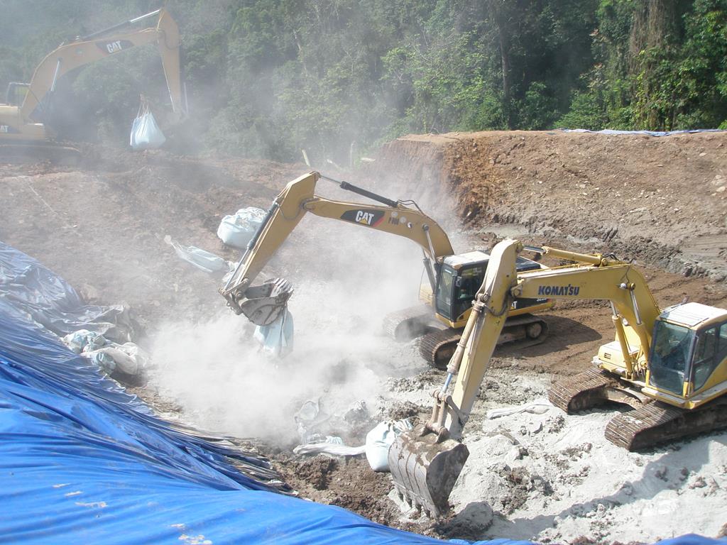 Soil cement stabilization is to improve soft and loose soils, expansive soils, sludge, and other weak grounds by mixing it with a certain amount of special cement and water using a rotary mixer, and compacted to high density, hard and semi rigid durable soil layer. Various types of cement stabilizer, in general provide stabilization by high hydration rate of soil water content, forming strong frameworks to strengthen soil structure, functioning in organic acid which inhibits cement hydration, and being expansible to compensate dry shrinkage. It can be applied to various types of problematic soil and relatively requires only short curing time.
Soil stabilization is frequently applied for road construction as a sub base layer reinforcing, subgrade protection or improvement, slope protection, fill and embankments, and structure bedding or foundation.
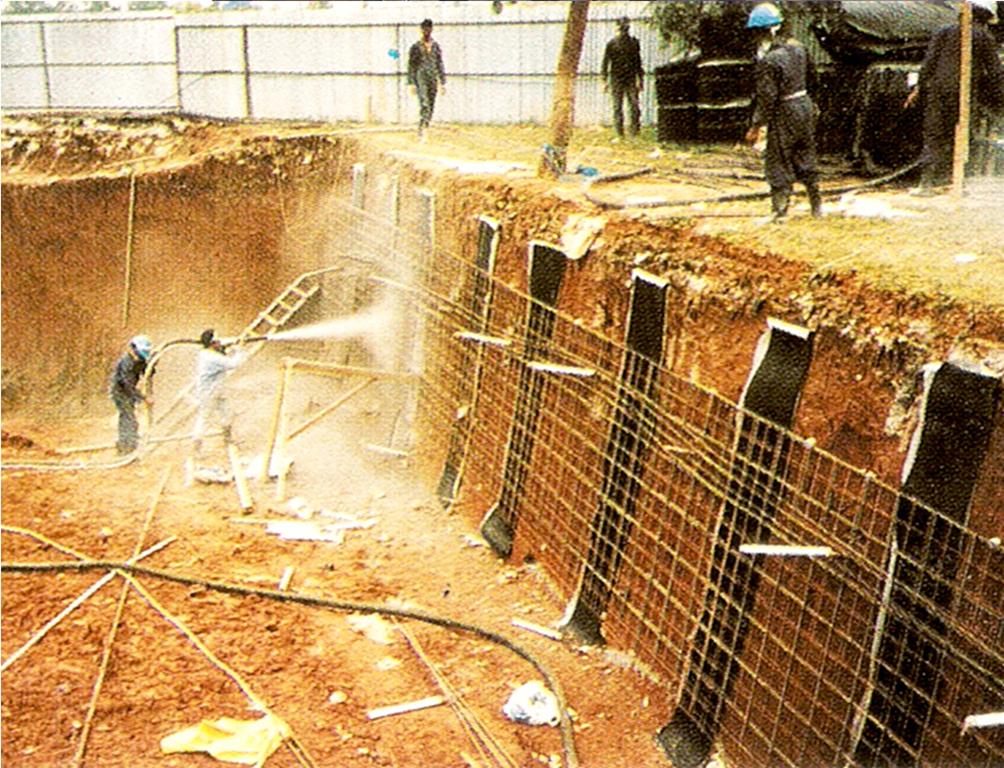 Soil nailing is a method of retaining wall for excavation or as a slope protection system, by reinforcing in-situ soil using grouted nail inclusions (reinforcing bar) and the surface between nails is stabilized by shotcrete. Shotcrete is a specialized method of applying concrete (reinforced with wiremesh) to a soil face using a high pressure spray. Soil nails provide passive resistance, as the soil mass deforms the nails become tensioned to arrest the deformations and stabilize the soil. Water can be accumulated behind the wall, care must be taken to release the water pressure commonly by using strip drains installed behind the wall from top down to drain the excess water or alternatively with weep or discharges pipes installed at intervals on the wall.
The main advantages of soil nail system are rapid and flexible construction methods, accommodating any variations in soil and rock conditions and work progress, can be used for wide applications, and relatively more economical compares with other retaining wall systems.
 Ground anchor or tied back anchorage functions as load carrying element, consisting essentially of a steel tendon inserted and grouted into suitable ground formations in almost any direction to obtain a specially formed bond length beyond zones of potential yielding of the soil mass. Its load-carrying capacity is generated as resisting reaction mobilized by stressing the ground (pre-stress) along the bond length, providing direct or active tension resistance to the anchored wall.
A ground anchor is commonly applied as tied back anchorage for retaining walls such as sheet pile, contiguous and secant piles, diaphragm wall and others. The use of ground anchors instead of strutting or raking shores to support retaining walls has the considerable advantage of providing a completely clear working area. In some cases, ground anchors are also often applied as pure tension piles such as tied back for raft foundation subjected to uplift.
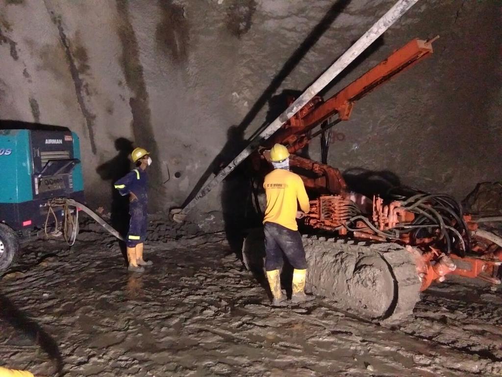 Rock bolt is a steel bolt inserted and anchored in a hole drilled into a rock mass to reinforce the surface or near surface stability of rock cliffs and slope excavations by restraint the rock mass and wedges together from falling or collapsing, and tunnel excavation from cave in. There are three methods of anchoring rock bolts; mechanical, grouted and friction. The first uses an expansion shell bolt which preload can be applied (active), grouted anchored is a fully grouted reinforcing bar, and friction type is generated from radial force over the whole length of bolt.
Rock bolt reinforcements have advantages that can be used in any face geometry and ground condition, simple and fast to install, and relatively economical. In areas of highly jointed or fractured rock, steel wiremesh can be used in conjunction with rock bolts to hold the small blocks of rock (rock fall).
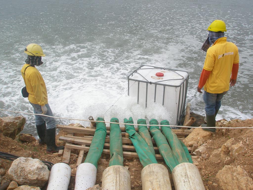 Dewatering is a technique to decrease water inflow and ground water table during construction excavation, thereby providing working space and increasing soil stability in the side and base of excavation. There are various methods; open sumps, well points, deep wells, horizontal wells and electro-osmosis (vacuum). Open sumps are necessary in any excavations, well points are multiple closely spaced wells generally suitable for large area of excavations, deep wells are more power full than well points, requiring only few holes thereby ease in excavation work and very commonly applied in deep excavations. The latter methods are more to remedy a difficult situation where other methods unsuccessful.
The choice of method depends to great extent of equipments, site conditions and soil characteristic, and often a combination method is inevitable. The amount dewatering works can be reduced by combining with seepage cut off such as impermeable retaining walls, groutings and freezing.
Since the beginning in early 80’s pt. pratama widya Tbk has established it self as a ground engineering solver to provide a one stop service in foundation and geotechnical engineering works from survey, design until construction. Our experiences are well diversed in various problematic ground engineering works such as: marine structures development (quaywall, jetty, wharf, harbour, skidway, drydock, etc), slope slide treatment and repair, foundation repair-strengthening and treatment, building underpinning, structure settlement treatment, access and hauling road in difficult ground and terrain condition, soil improvement including peat, slope stability protection, ground water management, retaining and curtain wall, and many other ground problems.


